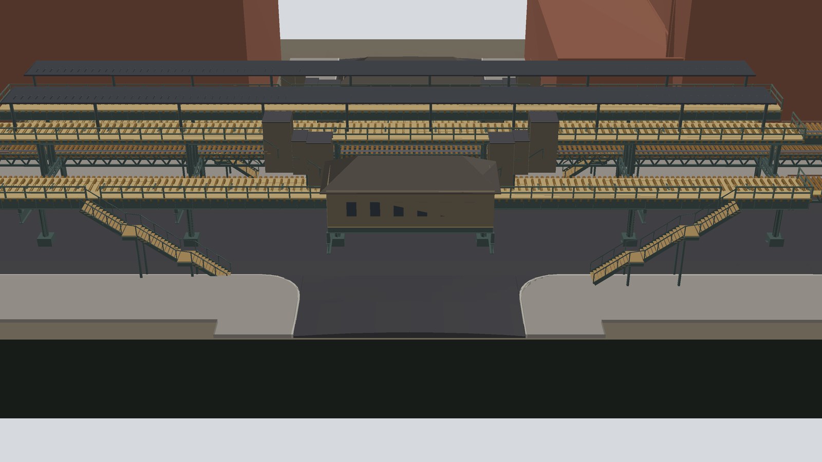
Of all the stations on Manhattan’s Eighth Avenue el, 145th Street is the one I keep coming back to. It was a hump: the express track in the middle climbed 11 ft 7 in above the locals to its own high-level platforms, and came down again on the far side. Two levels of platforms, station houses slung under the deck over the cross street, stairs coming down to the curb, all on the 1879 lattice ironwork. It is a wonderful thing to look at, and it fits in a straight line, which makes it a strong candidate for a real layout.
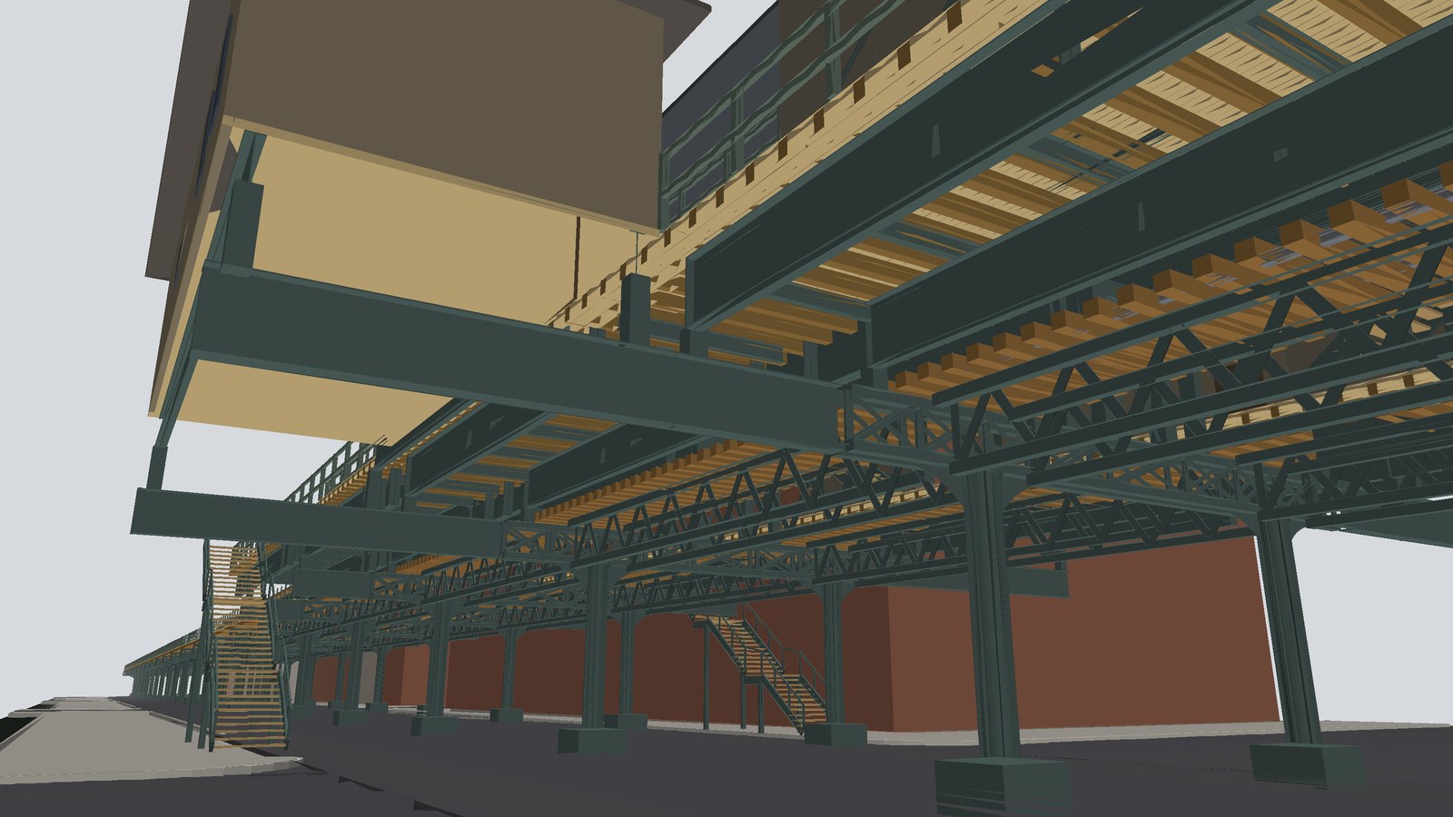
So I have used ElevateIT! to work it up as a study for a layout in OO (1:76.2), built with the west side of the avenue left open so that the model is viewed from the west, the way you would see it standing where the west-side buildings were.
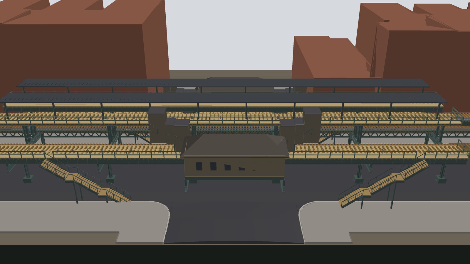
Real buildings, real heights
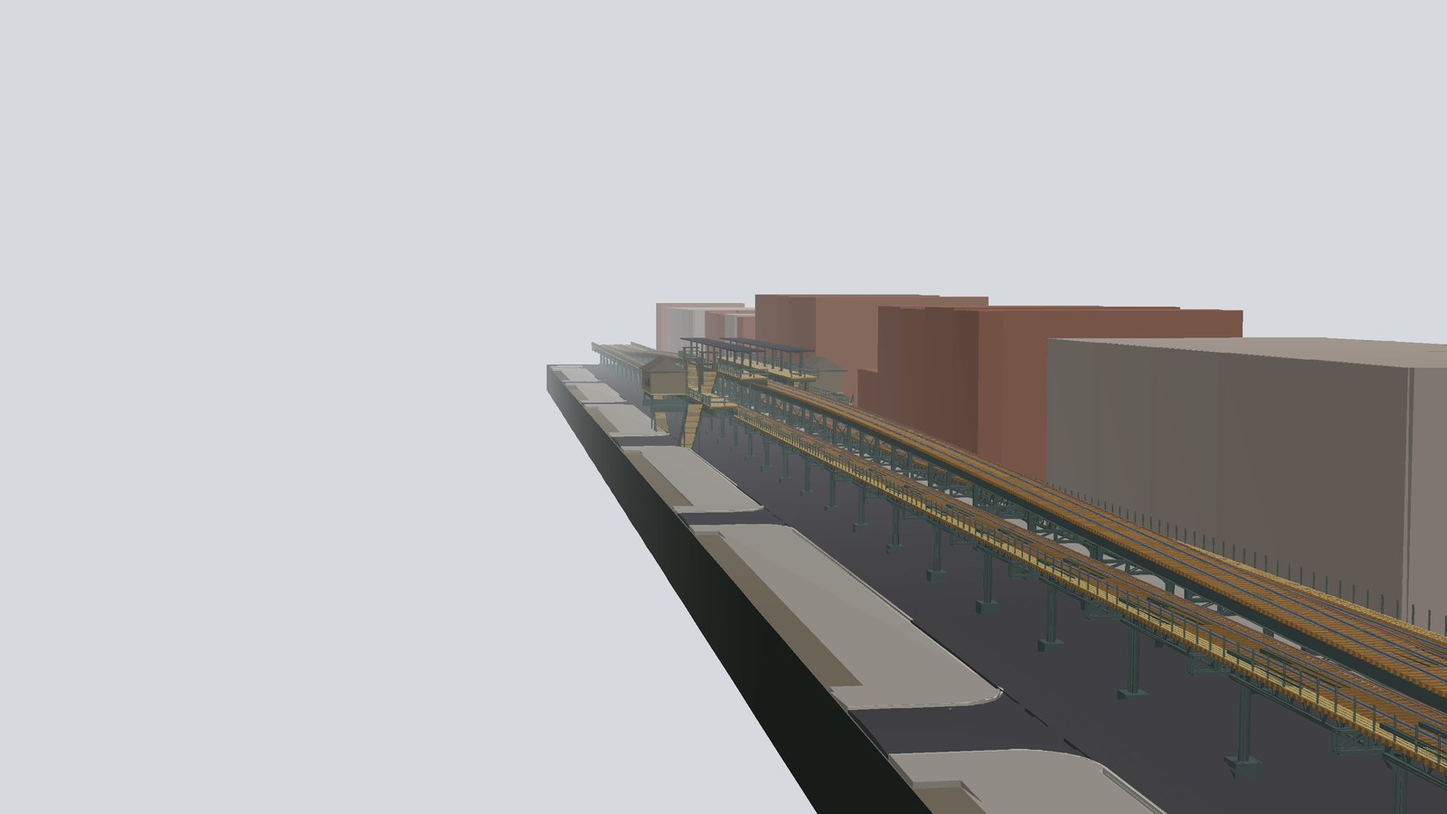
An el is only half the picture without the street it stood in, so the first job was the buildings. New York City publishes every building’s footprint with its measured roof height and the year it was built, and most of the 1900s–1920s walk-ups along this stretch still stand. Every building facing the avenue that was there by 1940 goes in at its real outline and height: mostly four to six storeys, 45 to 70 feet. Where a plot has since been rebuilt, the 1924 aerial photograph shows the blockfront built up, so a stand-in goes there, as tall as its neighbours and drawn paler so that you can tell it apart. In the ElevateIT! viewer each side of the street can be switched off on its own, which is how the west side came off for this study.
Then the street itself: the roadway, the granite curbs and the sidewalks, Eighth Avenue and the cross streets from W 142nd to W 148th. The curbs are the city’s own survey: a 60 ft roadway on the avenue, about 30 ft on the side streets. The camber comes from the period’s own practice: Rosewater’s 1902 formula for asphalt streets, from Judson’s City Roads and Pavements, gives the avenue a crown of 14¼ in, close to 5 mm at 4 mm scale, shaped to Judson’s own template, with curbs standing 6 in above the gutter.
How big, and where to cut it
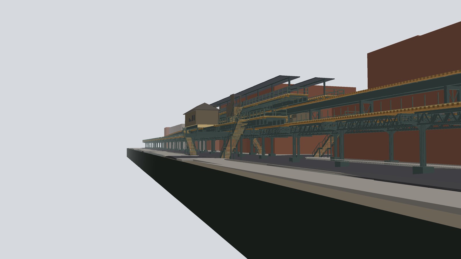
The whole thing is 1,700 ft of line, which at 4 mm to the foot is 6.8 metres long and 835 mm deep from the front edge to the backs of the east buildings (428 mm if they become low-relief flats). The rail is 80 mm above the street, the raised express a further 46 mm.
To plan the baseboards I drew it as an orthographic plan with the longitudinal elevation directly underneath, at the same scale, north to the left as you would see it from the west, with linear scales in millimetres and in prototype feet so that it can be measured however it is printed. Between the two run the things a joint has to dodge: every bent (they are 170 mm apart), the cross streets, the station, the hump, and the 156 mm modules that ElevateIT! prints its deck kits in.
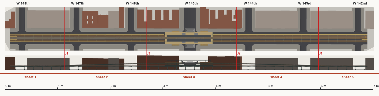
One way of dividing it is five boards of 936, 1,560, 1,716, 1,560 and 1,029 mm. Each joint falls on a module boundary, so no printed deck kit has to be cut across it, at least 24 mm from a bent and clear of the cross streets, and the station with its stairs and station houses sits whole on the middle board.
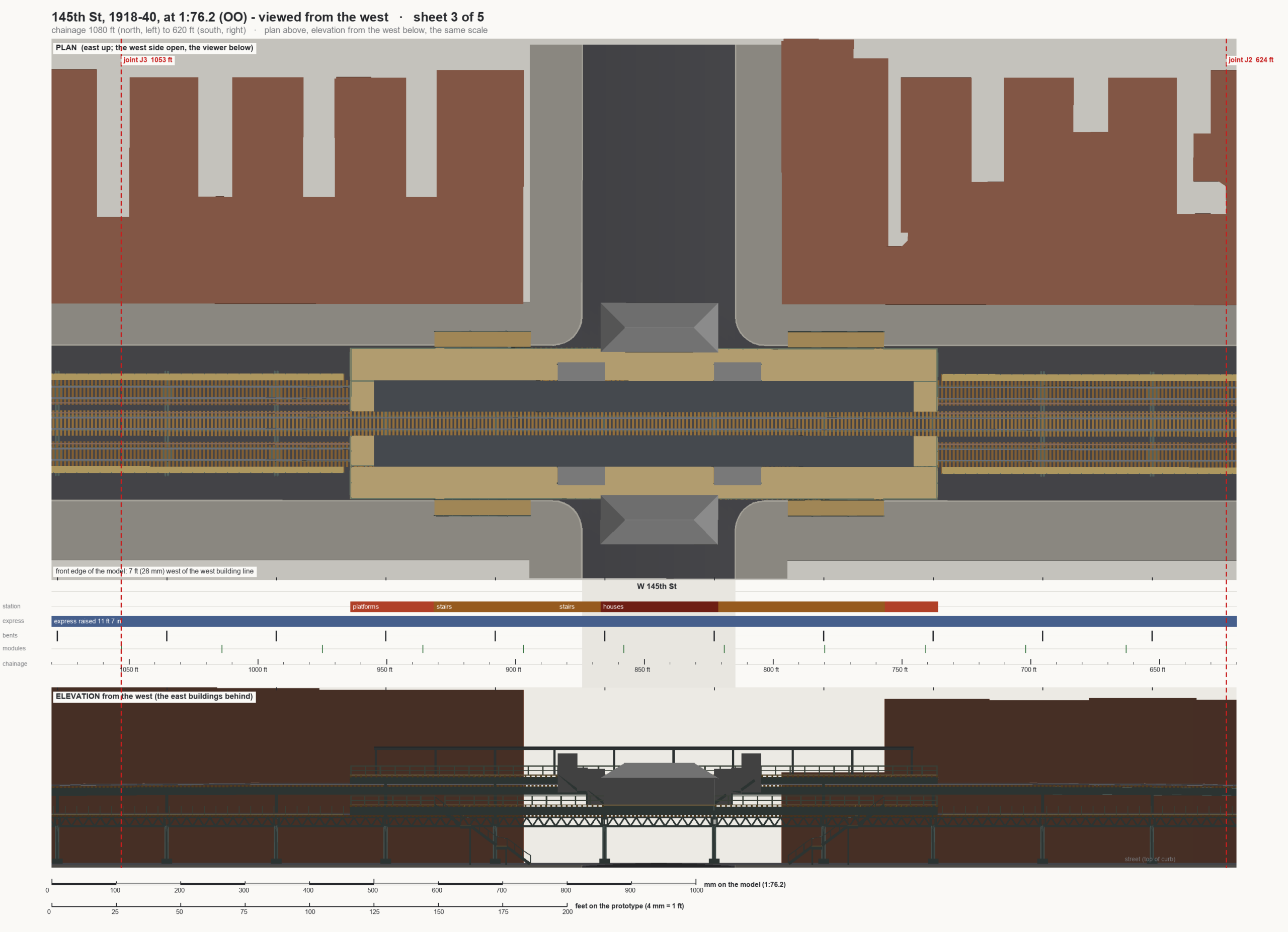
The full study has all five sheets, the remaining views and the joint positions in detail: open the 145th Street layout study.
What is real and what is not
The railway is ElevateIT!’s model of the station as the 1918 rebuilding left it, from the engineers’ own drawings in the ASCE Transactions. The buildings are measured where they survive and stand-ins where they do not. The curbs are today’s, which may differ from 1924’s by a few feet, and the street is drawn level, although W 145th in fact climbs towards St Nicholas Avenue. The renders are deliberately plain: they show form, size and position, not paint.
If you are tempted by an American el in 4 mm scale, or any other scale, I would be glad to hear from you on the contact page.
Leave a Reply